- Document History
- Subscribe to RSS Feed
- Mark as New
- Mark as Read
- Bookmark
- Subscribe
- Printer Friendly Page
- Report to a Moderator
- Subscribe to RSS Feed
- Mark as New
- Mark as Read
- Bookmark
- Subscribe
- Printer Friendly Page
- Report to a Moderator
Author(s):
Radu Florea – Student at TU Delft, The Netherlands
NI Products Used:
8 slot CompactRIO chassis with integrated FPGA, input modules for current, resistive and voltage sensors, high-speed digital output module, digital input module, LabVIEW development environment, together with the Real-Time and FPGA modules
The Challenge:
Developing a robust and flexible remote ground control system to control and monitor the Stratos II+ rocket filling and firing procedures during the engine test campaign and the launch campaign.
The Solution:
CompactRIO and LabVIEW provided the flexibility and the reliability for the time critical tasks associated with the remote control of the filling and launching of the Stratos II+ rocket, powered by one of the biggest hybrid rocket engines ever built by students.
Introduction
Project Stratos represents the forefront of technology developed by Delft Aerospace Rocket Engineering (DARE), a student society of TU Delft, having the ultimate goal of reaching space with a rocket designed, built and launched entirely by students. As an intermediate step to achieving this goal, the Stratos II+ rocket has been developed, and launched to a record breaking altitude of 21.5 km, setting a new European altitude record for amateur rocketry. A picture of the Stratos II+ rocket in the launch tower is presented in Figure 1.
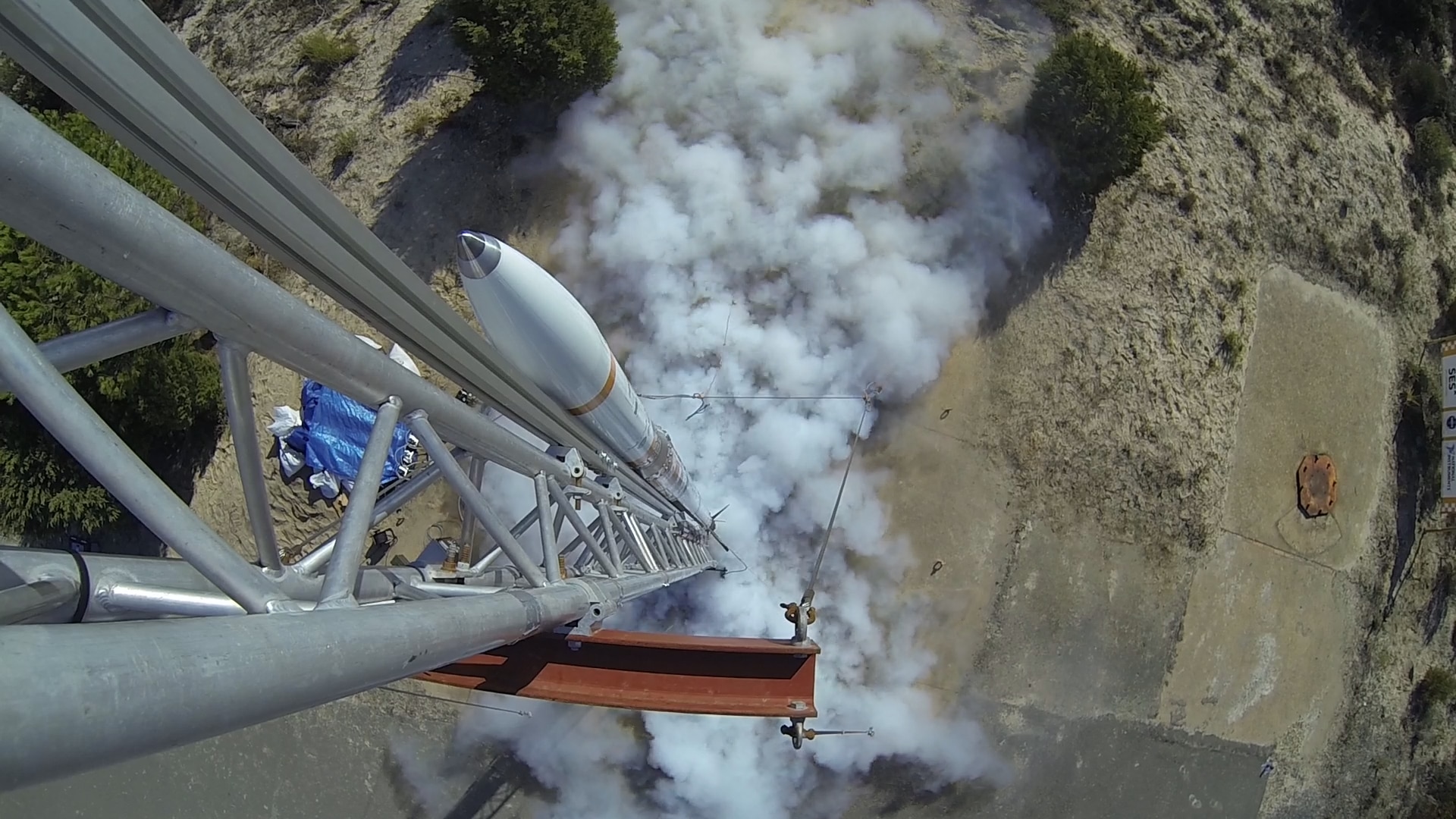
Figure 1. The Stratos II+ rocket in the launch tower
In order to ensure the successful launch and flight of the Stratos II+ rocket, a multitude of subsystems, have been developed, tested and integrated. These subsystems range from video telemetry transmitters, separation mechanisms to propulsion systems and more. A critical subsystem, both during the propulsion system test campaign, as well as throughout the Stratos II+ launch campaign, is the CompactRIO-based ground control system (GCS). The GCS handles all engine-related operations, such as filling, monitoring, ignition etc.
Requirements Overview
The Stratos II+ rocket is highly complex. In order to ensure the safety and the success of the mission, all subsystems that are developed must work as reliably as possible. There is little room for error in rocket science.
In order to be able to perform all test and launch operations as safe as possible, a remote system (i.e. a ground control system) is needed. This system must be able to easily communicate with the rocket, gather data (i.e. engine pressure information, rocket weight, error messages etc.) about the status of the subsystems, relay this data back to the remote station, all while performing time-critical tasks that are crucial to the success of the test/launch.
Developing a rocket is subject to many changes during design, and especially during testing, as there will always be different types of problems that need to be solved in between tests, giving little time for the development of a dedicated custom electronic subsystem. Furthermore, the ground control system is intended to be used for both for the engine test campaign and for the launch campaign, thus, it must be easily adaptable.
The GCS must be modular so that it can be easily adapted or extended in order to accommodate for any new requirements that may arise. At the same time it must be a robust system, since it will be exposed to the extreme environment that rocket launching and testing. Reliability of the GCS is crucial in order to ensure a high degree of safety in all conducted operations.
Propulsion System Development
Stratos II+ is powered by the DHX-200 Aurora rocket engine, a hybrid propulsion system making use of liquid nitrous oxide as oxidizer, in order to burn the solid grain fuel (a mixture of sorbitol, paraffin, and aluminium powder). The system makes use of the self-pressurizing properties of nitrous oxide for oxidizer feeding.
The Aurora has a peak thrust of 12 kN (enough to lift a car), and specific impulse Isp = 205 s, making it one of, if not the biggest hybrid engine ever built by students. It is designed to run for 25 s, with an average thrust of 8 kN, delivering a total impulse of 180 kNs.
The Stratos propulsion team has undergone a total of 14 engine tests with the DHX-200 Aurora over a span of 2 years, performing numerous design changes and improvements throughout the tests. The propulsion system test stand, at the TNO, Rijswijk facilities, is presented in Figure 2.
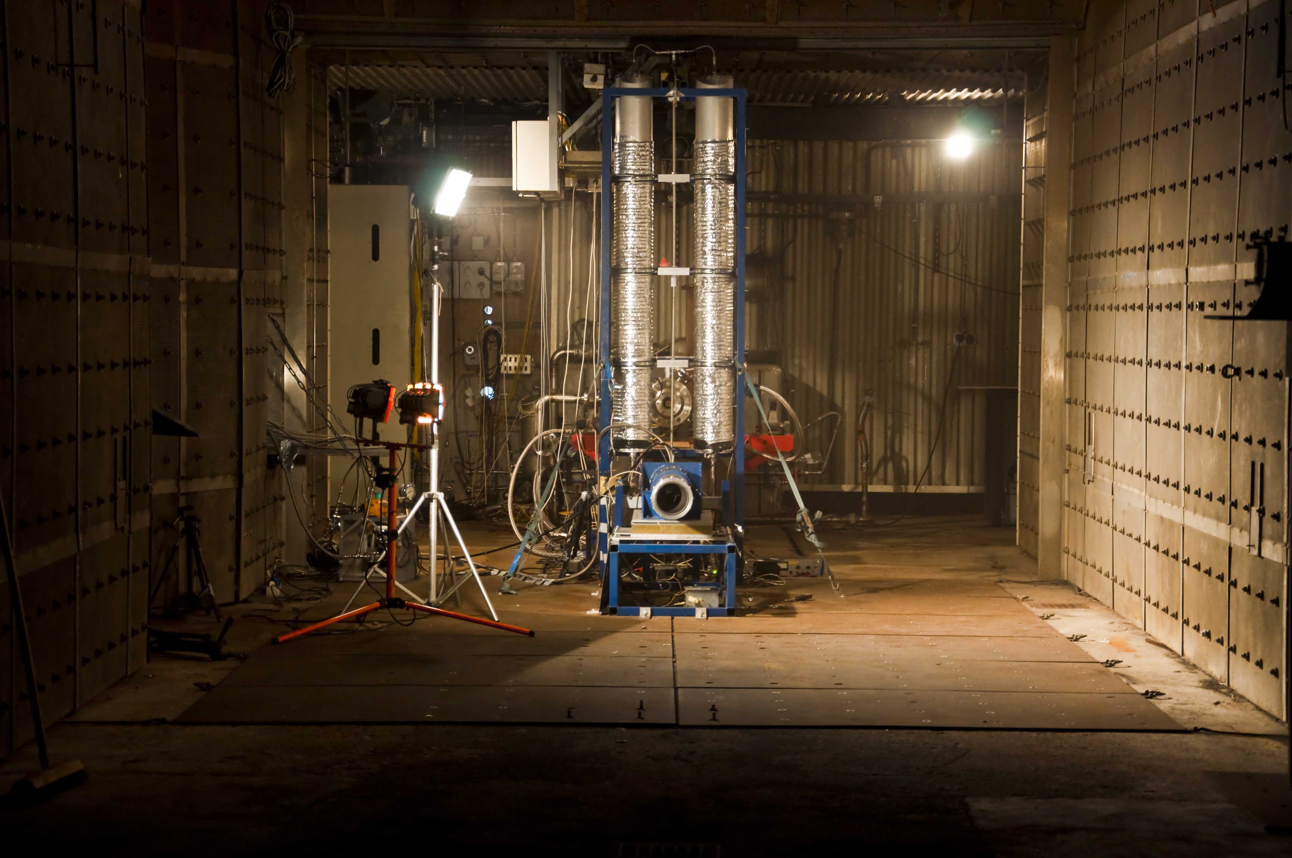 Figure 2. DHX-200 Aurora ready to be fired at TNO, Rijswijk
Sensor and Actuator Subsystems
The feed system for the test campaign is presented in Figure 3. The feed system components that are controlled through the GCS, together with their abbreviations, are presented below:
- FV-1 "Fill Valve 1" is the main actuator for filling the run-tanks. It is a combination of a pneumatically actuated 1/2" valve and a small electrically actuated solenoid valve. Actuation gas is nitrogen at a maximum of 8 bar, originating from a separate N2 gas cylinder with a gas regulator. It is a normally closed (NC) valve.
- DV "Dump Valve" is similar to FV-1. It is used to dump the nitrous oxide from the run tanks in case of unforeseen issues or a power failure. It is a normally open (NO) valve.
- BV "Bleed Valve" is a normally open (NO) solenoid valve used to vent gaseous nitrous oxide from the top of both interconnected run-tanks during the filling procedure. It also is a safety measure that automatically vents the run-tanks in case of a power failure.
- MV-1 "Main Valve 1" is a 1/2" ball valve that is actuated by a servo.
- MV-2 "Main Valve 2" is a 1/2" ball valve that is actuated by a pneumatic actuator. It adds redundancy to the main oxidizer line in case of an emergency engine shut down. It is a normally closed (NC) valve.
- IV-1, IV-2 "Ignition Valve" are two normally closed (NC) solenoid valves connected in series for redundancy and actuated at the same time. Used for priming the combustion chamber with nitrous oxide prior to ignition.
- XV "Extinguisher Valve" is a normally closed (NC) solenoid that dumps nitrogen into the combustion chamber after motor cut-off to properly extinguish any remaining combustion.
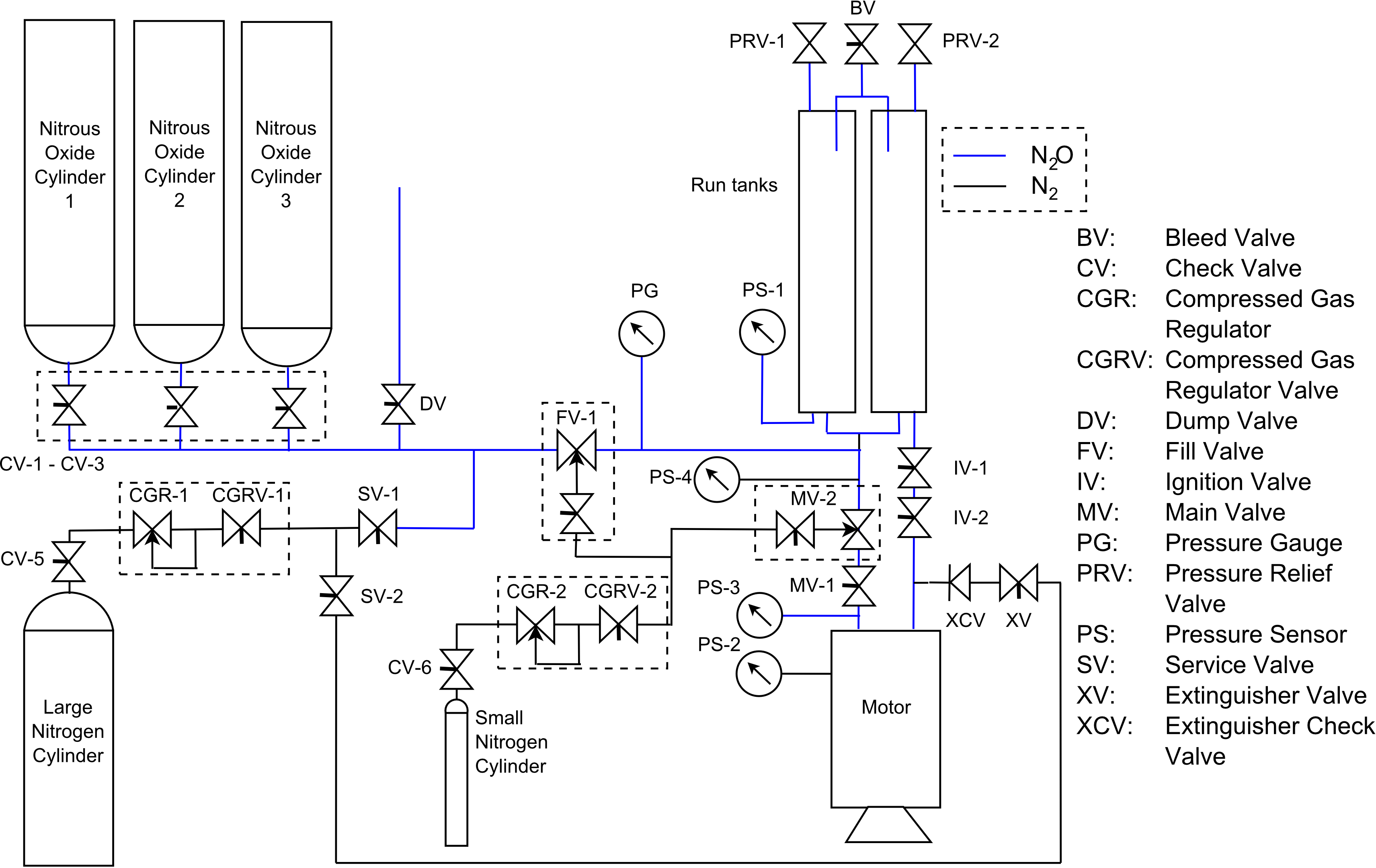
Figure 3. Feed system layout for the test campaign
Two load cells are used in order to gather information on the mass of the oxidizer tanks and the thrust generated by the engine. Pressure sensors are used to measure the oxidizer feed pressure, feed system state, and combustion pressure, during engine operation. The load cell and the pressure sensors are sampled at a high data rate, enabling the detection of any instabilities during the engine tests.
Eight thermocouples are used to obtain thermal information on the combustion chamber, in order to detect possible thermal issues during combustion. Relay contact sensors are used to monitor the switching of the relays used in actuator control. This is done to detect any failure that might occur within the actuation subsystem.
The location of some sensors on the test set-up is illustrated in Figure 4 (PS-4 has been left out, since the actuators and feed system are not drawn in the figure).
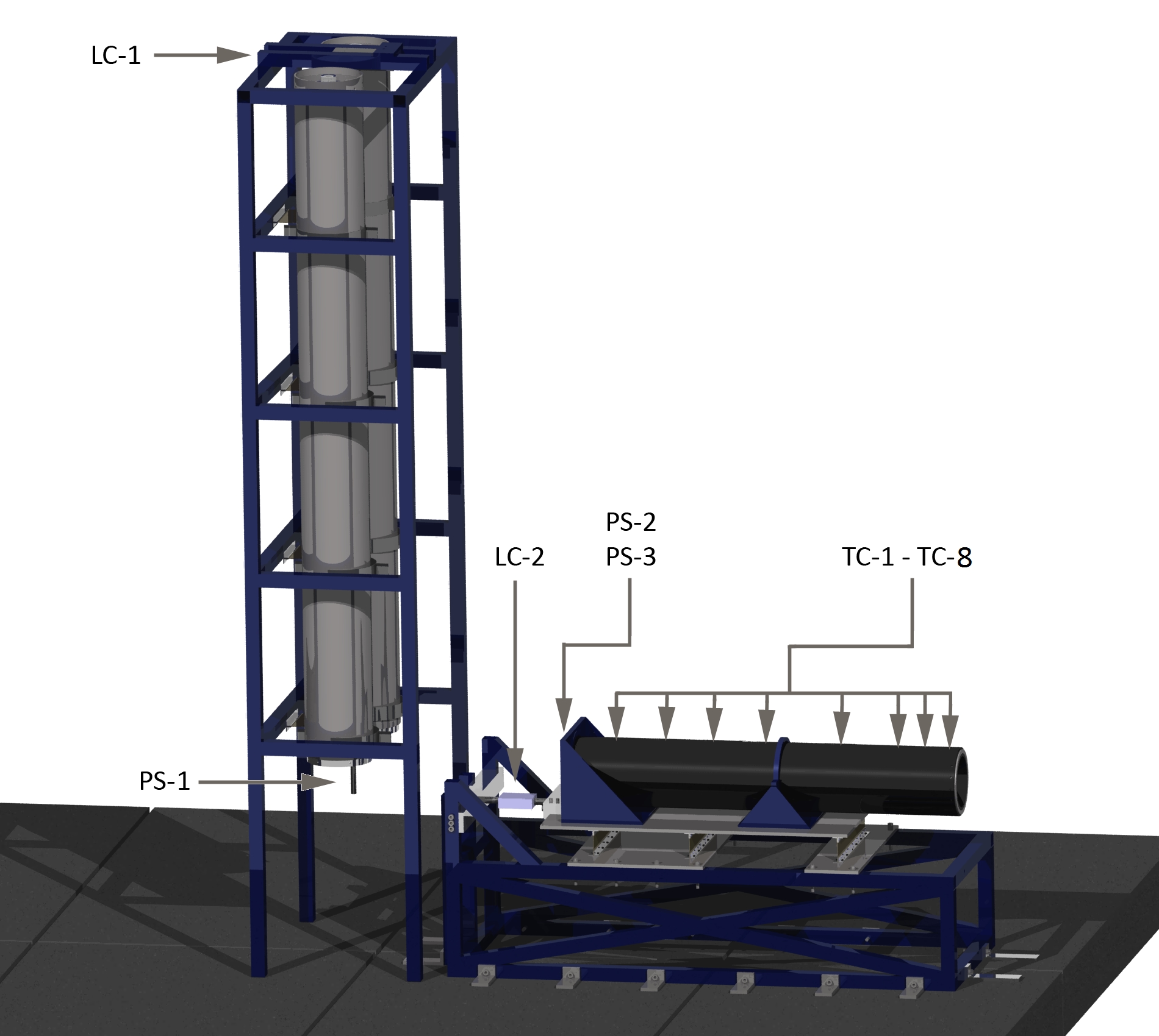
Figure 4. Isometric view of the test setup with indicated location of sensors (hoses and actuators are not shown)
Monitoring and Control Software
The monitoring and control software is the part of the GCS that brings everything together, making sure that all conditions for a safe and successful test are met. It acquires data from the modules, processes it, and performs real-time engine control actions based. The software functions are presented below:
- Automated pre-flight/pre-test systems check - this operation is performed in order to verify the full functionality of the engine firing procedure, as well as to detect and localize any actuator malfunctions such that the test/launch will be successful. This operation is performed using the timer functions of the real-time controller, and by making use of the information provided by the RC-1 to RC-9 relay switches.
- Oxidizer tank filling and pressurization - these operations are initiated after all systems have been set up, and the pad has been cleared of all personnel. First, the tank filling (up to a weight of 80 kg) operation is performed. Based on data from the run tanks pressure sensor, and the weight load cell, the bleed valve is opened, in order to vent the tanks, whenever the mass differential over a time period of two minutes is less than a predefined value (based on experience from tests). The pressurization operation follows, during which the heater cables are turned on until a pressure of 60 bar is reached.
- Time critical engine start-up sequence - in order to start up the engine, a time critical sequence, initiated by the GCS operator, is conducted by the software. The sequence involves squib activation, combustion chamber priming and main valve opening. If any of these steps is not within the allowed time frame, it will result in an engine misfire.
- Time critical runtime engine diagnosis - this operation is performed during engine runtime, and it involves real-time monitoring of the pressure and temperature levels during the propulsion system's operation. By processing this data in real-time, the software is able to detect possible engine malfunctions and perform an immediate shut down.
- Emergency shutdown sequence - this sequence is performed in the case of an engine malfunction during its operation. It involves closing the main feed line valve, and purging the combustion chamber with nitrogen.
Preparation for the Test Campaign
Having set all the requirements for the new ground control system, work on the system started in preparation for the final engine test campaign. An entire electrical system has been built around the CompactRIO, focusing on general system robustness. Pictures of the GCS development, assembly and testing are presented in Figure 5 and in Figure 6.
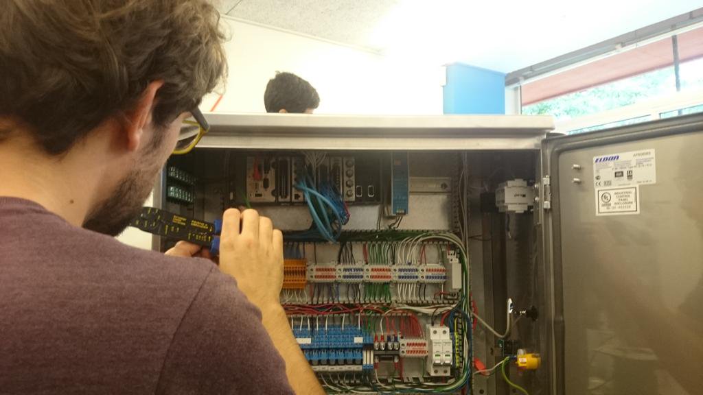
Figure 5. Ground control system close to being ready
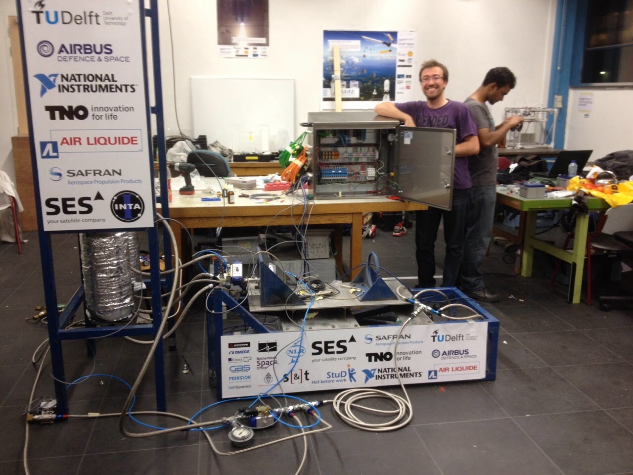
Figure 6. Testing all subsystems in preparation for the test campaign
Outcome of the Test Campaign
Over the span of two years, and throughout 14 tests, the propulsion team has worked tirelessly to improve the DHX-200 Aurora. Throughout the development of the engine, numerous failures have been encountered and overcome. Failure modes such as grain cracking, chamber thermal failure, combustion instabilities, and, even, nitrous oxide decomposition.
Overcoming all the hurdles in the development of the engine has been an immense challenge, however, with the last test of the engine, all problems have been dealt with, and the Aurora ran for after which the fuel ran out, resulting in the rupture of the chamber, due to its walls being directly exposed to the hot flames. The video of the last test is shown below:
Throughout the test campaign, the GCS proved that it is a highly robust and reliable system. This allowed the team to focus better on solving the failure modes of the engine, rather than trying to fix faulty circuitry. Furthermore, it allowed us to quickly adapt the software to new requirement. The LabVIEW user interface provided a good overview of the engine's status throughout the tests, it was clear, simple and easy to use by all the team members.
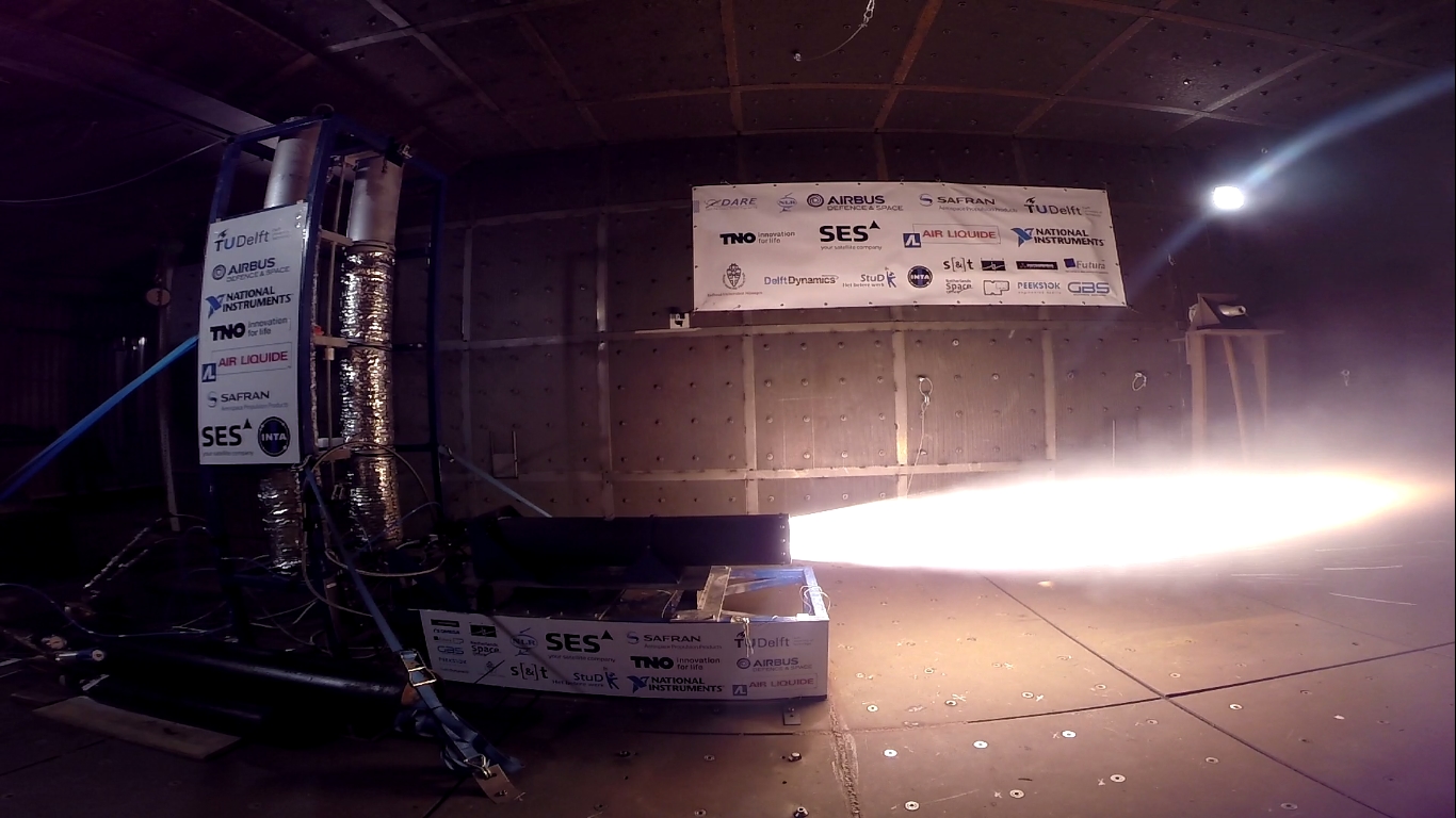
Figure 7. DHX-200 Aurora during test fire
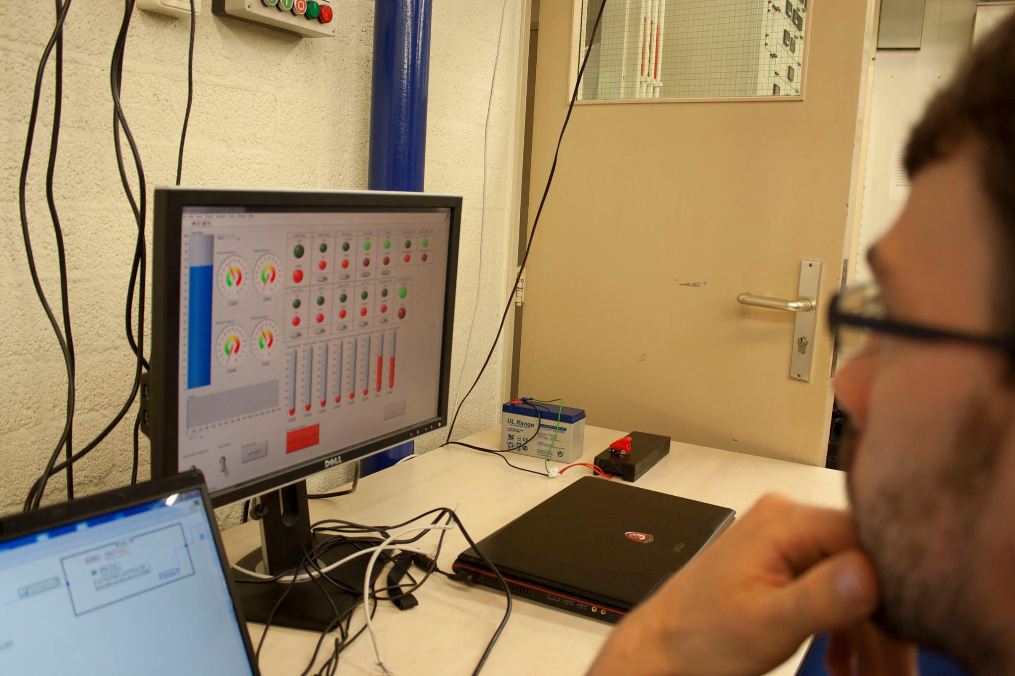
Figure 8. Propulsion team member monitoring the engine status during testing, using the LabVIEW user interface
Stratos II+ Launch Campaign
Having proven the flight readiness of the engine, the Stratos II+ team now focused on the launch campaign, taking place in the south of Spain, throughout the month of October.
Preparation for the Launch Campaign
Having a variety of subsystems that need to be integrated, certain adaptations need to be made to these systems for them to be able to function as a whole. The GCS, thus, needed to be adapted, hardware and software wise, in order to be able to communicate with the rocket and perform a different set of tasks than the ones performed during the test campaign. Furthermore, the feed system (presented in Figure 9) layout has been altered for the flight version.
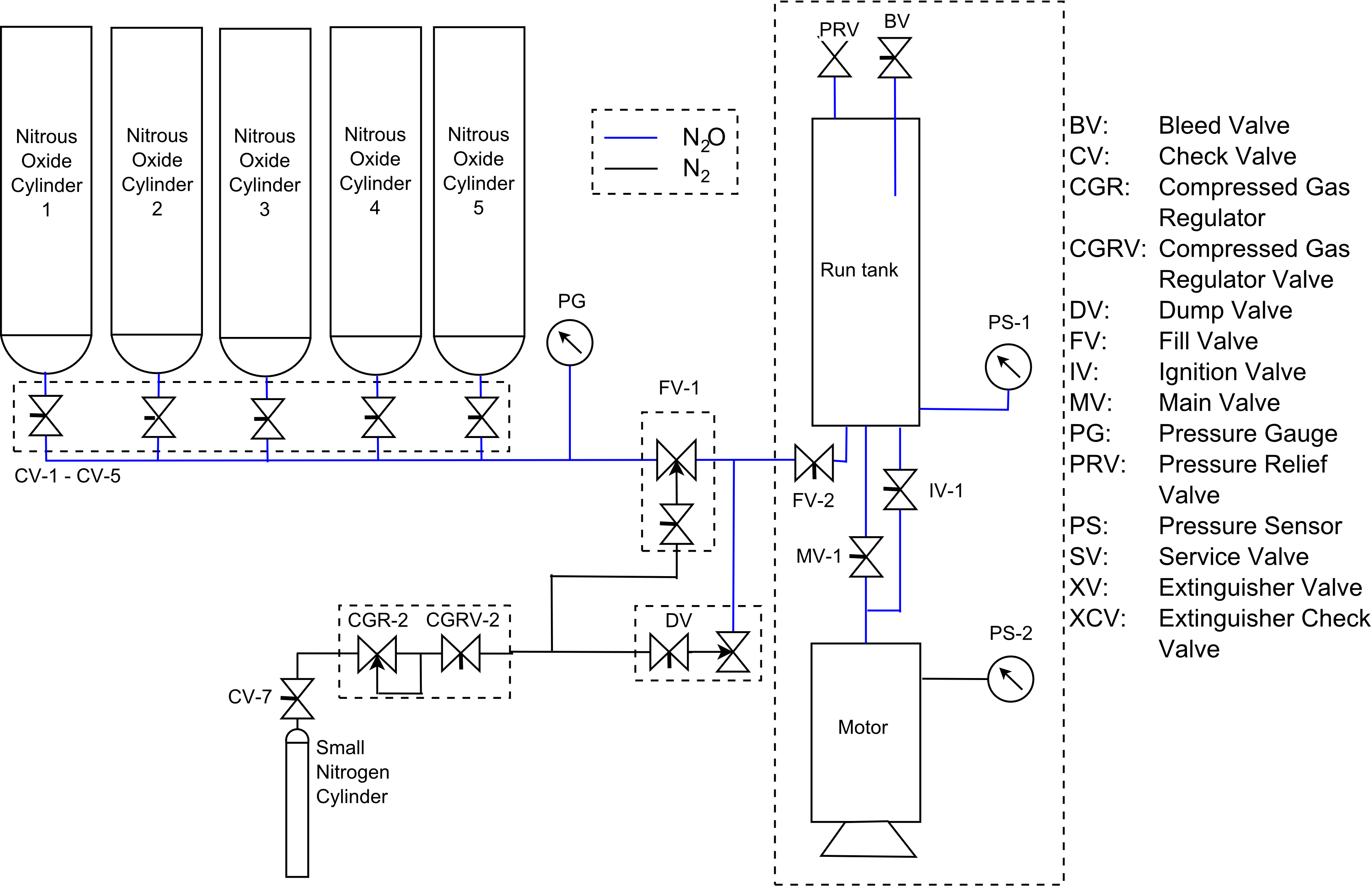
Figure 9. Feed system layout for the launch campaign
As it can be seen from the figure, the instrumentation on the engine has been reduced, and an extra servo-actuated filling valve has been added (FV-2). Furthermore, a new voltage sensing module has been installed in the RIO chassis, in order to measure and diagnose actuator circuits. Once again, the modular architecture of the CompactRIO proves to be of great benefit, allowing for the hardware changes to be conducted in a quick manner, and without any complications.
The software running on the GCS has been extended with the DARE proprietary Launch-Box Protocol, and a register-like memory map, so that the system will be able to communicate with all other subsystems and route information through to the control panel (CP). The protocol has been implemented over the serial RS-232 communication bus, using LabVIEW, which allowed a quick and straight-forward implementation of the new software.
Rain, Sun and Fire
The Stratos II+ launch campaign spanned three weeks, in the month of October, at the INTA (Instituto Nacional de Técnica Aerospacial) base, in Mazagón, southern Spain. Throughout these three weeks, all system and payload testing and integration has been performed. Figure 10 shows the ground control system being set up on the launch pad.
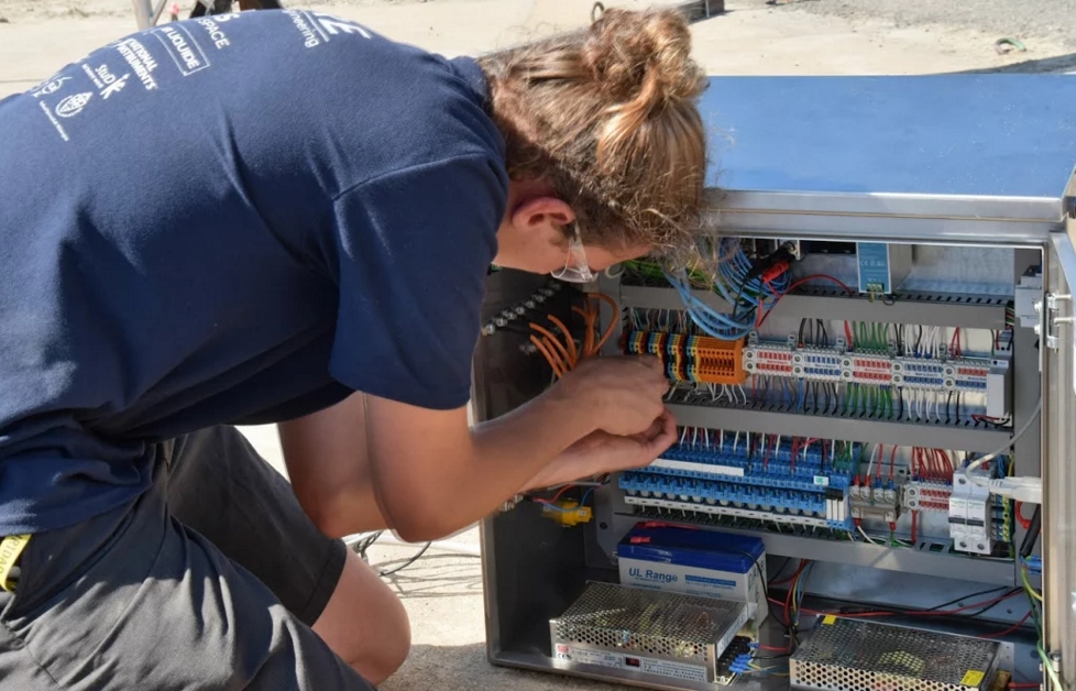
Figure 10. Compact RIO-based ground control system being set up on the launch pad
With all the subsystems ready, the rocket set up in the tower, the go-for-launch is given. The procedures went smoothly, and the rocket launched to 21.5 km! In Figure 11, the lift-off of the rocket is presented.
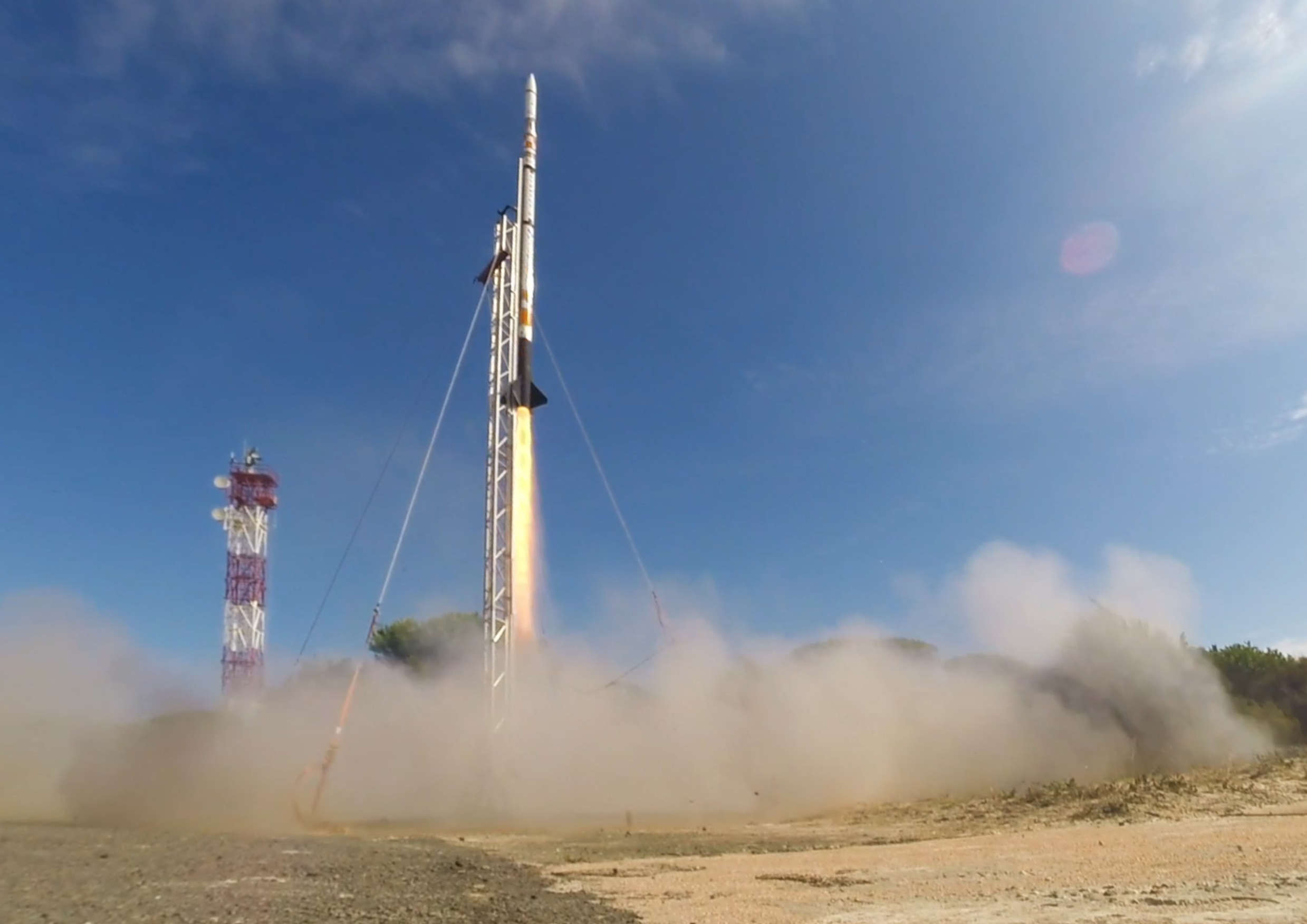
Figure 11. The Stratos II+ rocket lifting off the launch pad
Furthermore, a compilation video of all the launch campaign footage is shown below:
The Benefits of CompactRIO and LabVIEW
The RIO architecture was of great benefit to the entire project, as it allowed for swift changes in the ground control system, without having to resort to "hacked" solutions. It, thus, resulted in an increased system reliability, and increased confidence of the team in the GCS. The straight-forward connection of sensors and actuators to the system allowed more members to work with the system, reducing issues resulting from faulty connections.
Developing the software in LabVIEW represents a great advantage, since the monitoring and control software could be developed in a short amount of time, due to the intuitive graphical programming style. The debugging features of LabVIEW were of great use especially when implementing the Launch-Box Protocol, as it allowed for the evaluation of the message string at every step of its encoding and decoding. Furthermore, the user interface could be adapted at any time, giving it flexibility in terms of the information that was desired to be displayed.
Basing the ground control system on the CompactRIO has greatly reduced the development time that would have been needed if a custom solution for the GCS would have been chosen. This has also allowed the team members to spend more time on analysing information, in order to improve on the efficiency of the rocket's subsystems, without having to be concerned with a badly functioning GCS.
Conclusion
The launch of the Stratos II+ rocket represents a great achievement for the entire team. The experience gained throughout the project is invaluable. We were able to develop highly sophisticated systems, conduct propulsion tests and launch operations in a professional manner, leading to a better understanding of professional life after university.
Having the CompactRIO as the basis for the ground control system, greatly reduced the development time for the GCS. It allowed us to have a fully functional, robust, modular system within four and a half months after the start of the development. Furthermore, the ease of programming in LabVIEW reduced the development time even further. Developing a custom solution for the GCS would have resulted in at least ten-eleven months of designing, building and testing the custom equipment and software. Thus, through the use of National Instruments products, the development time has been reduced by more than.
Using the CompactRIO and LabVIEW reduced the implementation issues, thus, the team was able to focus on improving the design of the rocket, the efficiency of the propulsion system etc., effectively allowing us to become better engineers.
Project Stratos has been an incredible and unforgettable experience. The Stratos II+ team is presented in Figure 12.
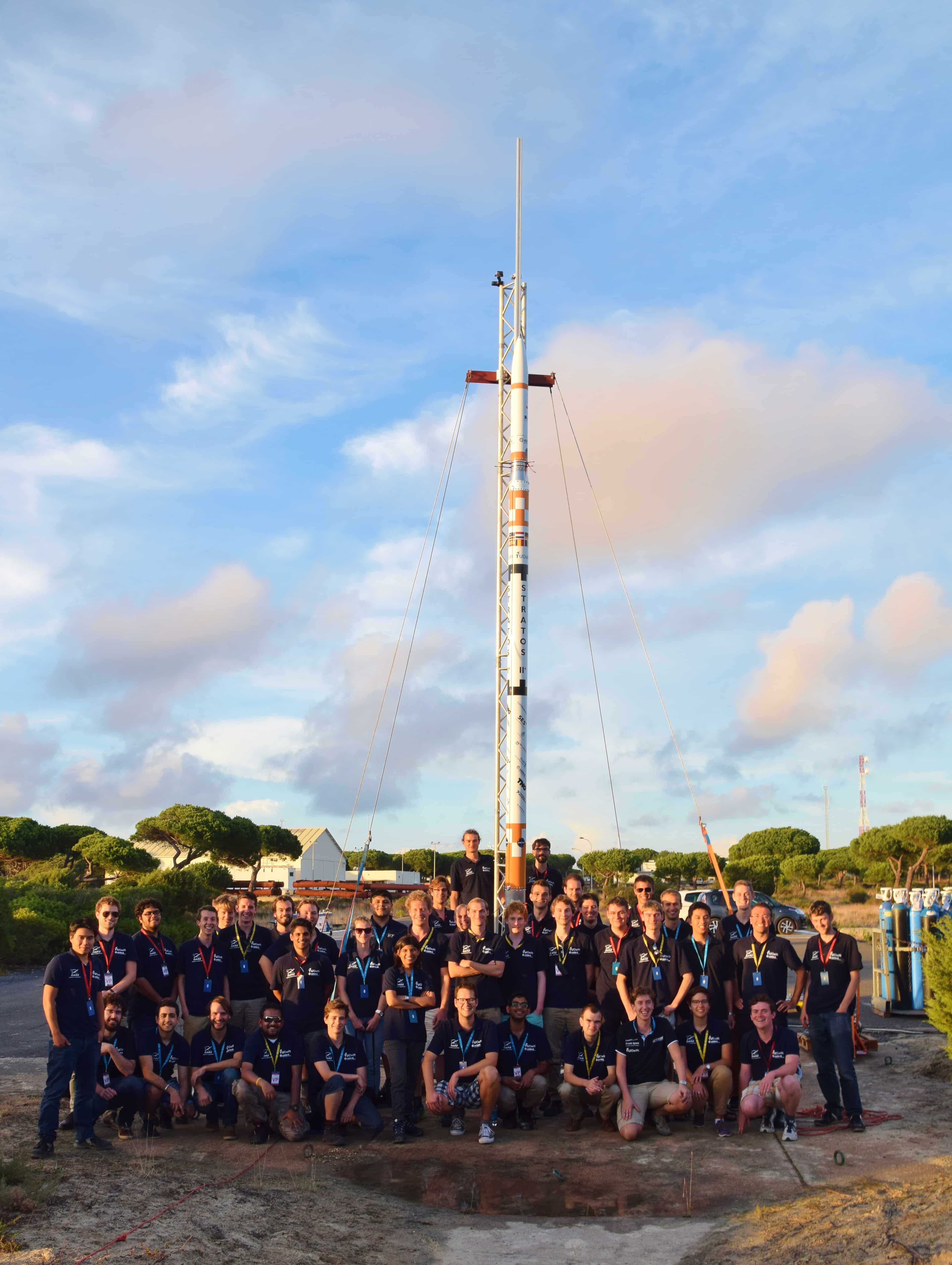
Figure 12. The Stratos II+ team on the launch pad
- Mark as Read
- Mark as New
- Bookmark
- Permalink
- Report to a Moderator
HUGE congratulations to the DARE team. This is a phenominal engineering achievement.
Senior Marketing Engineer, National Instruments
Connect on LinkedIn: https://www.linkedin.com/in/richard-roberts-4176a27b/
- Mark as Read
- Mark as New
- Bookmark
- Permalink
- Report to a Moderator
Thank you, RER!
- Mark as Read
- Mark as New
- Bookmark
- Permalink
- Report to a Moderator
Thank you, Beejal!
- Mark as Read
- Mark as New
- Bookmark
- Permalink
- Report to a Moderator
Guys, I notice that the final embedded video (the "after video") is broken. I believe this is the video... https://www.youtube.com/watch?v=WWNzVV-Pr_I
The video is beautifully produced - could you relink please!
Senior Marketing Engineer, National Instruments
Connect on LinkedIn: https://www.linkedin.com/in/richard-roberts-4176a27b/
- Mark as Read
- Mark as New
- Bookmark
- Permalink
- Report to a Moderator
Thank you for noticing! It should be fixed now.
- Mark as Read
- Mark as New
- Bookmark
- Permalink
- Report to a Moderator
Great work!
