Posted to News on 20th Nov 2012, 11:47
How to select linear actuators for positioning systems
Specifying linear motion systems is not the 'black art' many engineers think it is. Mike Hughes, an Applications Engineer at Schaeffler UK, provides some useful tips and guidance for engineers on how to select the most suitable linear actuators for single- and multi-axis positioning systems.

Many engineers are still not confident when it comes to selecting linear actuators for motion applications. Some avoid linear motion systems altogether and revert to traditional rotary alternatives, even if that means over-engineering a system. In reality, though, specifying linear motion systems is not the 'black art' that many engineers think it is.
On most occasions, if engineers just pick up the telephone and discuss their application with a linear systems supplier, potential issues can be resolved and a suitable approach found. By talking through their concerns with an experienced linear application engineer, engineers can often save themselves a lot of wasted design effort or prevent the system from being too costly (over-engineered). The supplier can also inform the customer exactly what is and what is not possible in terms of linear motion systems, and can provide valuable advice and guidance on integrated drives, mounting arrangements and fixings.
Terminology
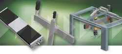
In selecting linear actuators for single- and multi-axis positioning and handling systems, terminology can be confusing. Many engineers commonly refer to linear actuators as 'linear modules', 'driven linear systems' or 'linear X-Y tables'. These types of systems, which we will refer to as 'linear modules', normally incorporate a number of different linear drives and actuators, including belt-driven linear actuators, ball screw-driven linear actuators, linear tables and linear motors.
The factors below need careful consideration when selecting a suitable linear module for a single-axis, two-axis or three-axis positioning system.
System configuration
System configuration, including the number of axes of motion, is often the first factor that needs careful thought. The most common are two-axis (X-Y) configurations, but less complex single-axis applications and three-axis configurations are also possible.
Orientation and mounting
System orientation and mounting are also key factors. In a single-axis linear system, this is fairly straightforward but, in multiple-axis systems, this becomes more complex. Factors to consider here include the direction of travel of each axis. Does the load need to be moved simultaneously in multiple axes or does each axis move individually? Does the system require a moving carriage (standard) or a moving rail? Are the axes vertical, horizontal or inclined? Are the mounting positions of each actuator at 0, 90 or 180 degrees to the horizontal?
Other factors to consider include the spacing between support points in the system, as well as how rigid and flat the supporting surface is for the entire linear positioning system.
Mass and centre of gravity
The mass (and geometry) of the object to be moved, and the position of its centre of gravity as it moves relative to a co-ordinate or datum point on each axis, must also be calculated. Clearly, as a mass is accelerated or decelerated along multiple axes of travel, the position of its centre of gravity relative to each axis will change. This needs careful consideration so that the moment loads at multiple points in the system can be established. Often, calculating the best-case and worst-case scenarios (using design calculation software such as Schaeffler's Linear EasySolution) and then averaging these is sufficient for most applications.
Other questions here include whether sufficient load-carrying capacity (including static safety factors) has been allowed in the system to cater for instantaneous moment loads. Also, are there are any overhung loads in the system, including drives, electric motors or motorised gearboxes?
Stroke lengths
The 'effective' and 'total' stroke length for each axis is also critical. With ball screw-driven linear actuators, for example, the stroke length is limited to the length of the ball screw itself. Therefore, maximum stroke lengths tend to be around 3m. But with belt-driven systems, there are no such restrictions and so stroke lengths can be higher than this, up to as much as 20m if required. If linear motors are specified, in theory, stroke length is unlimited but, in reality, lengths above 10m are rare.
Accuracy and repeatability
Depending on the application, accuracy and repeatability will differ greatly between applications. Most customers know what their accuracy requirements are. For example, if the actuator is for an automated pick-and-place machine, then it is likely that high repeatability and accuracy are required. Typically, the accuracy of a ball screw-driven linear actuator is 0.16mm per metre with repeatability of +/-0.01mm. For belt-driven actuators, typical accuracy is around 0.5mm per metre, with repeatability of +/-0.10mm.
Traverse speeds and accelerations
The limiting factors for traverse speeds and traverse times are the ball screws and/or the bearings. Typically, with ball screw-driven actuators, maximum speeds of 3m/s are possible. For belt-driven actuators with track roller guidance systems, the maximum speed is around 8-9m/s. If recirculating linear bearings are used with belt-driven actuators, maximum speeds are similar to their ball screw equivalents (3m/s).
Acceleration itself is not normally the defining issue in multi-axis positioning systems; it is the loads due to these accelerations in the system that are critical. The highest acceleration of any linear actuator to date is around 40m/s2, although typically accelerations are more likely to be much less than this, often between 0.5m/s2 and 5m/s2. Deceleration is also important, particularly if there are emergency stops required in the system.
Cycle time requirements
Cycle times dictate the life of a linear system. For example, a positioning system such as a tool changer on a machine tool might change the tool five times per hour. How is this cycle time going to vary from day-to-day, and how will this affect the fatigue life of the linear components within the system? If the customer needs the system to last for a minimum of 10 years, changing the tool five times every hour may not be an issue. But if the tool is changed 10 times per hour, a different type of linear system may be required in order to guarantee a 10-year operating life.
External loads and forces
This includes external impact forces on the system such as stops or human interventions. Is something pushing or pulling on the load to be moved, or does the load to be brought quickly to a stop at the end of its travel? For example, a drive may bring the linear actuator to a stop or a 'home' datum position. How this is achieved and how this affects the loads on the mass to be moved are key considerations. A safety stroke factor may also be required here.
Environmental factors
Environmental factors such as temperature, humidity and contamination (eg dust, oil, water, washdowns, chemicals and coolants) will also affect the choice of linear system. A dusty working environment may require the customer to implement external bellows or dust-extraction devices for the linear system. Linear actuators can be protected from the environment by incorporating special seals, corrosion-resistant materials and coatings, special greases or by using plastic parts where necessary.
In medical applications, the overall noise of the system may be a factor that needs addressing. A lower-speed linear actuator may be appropriate here but, if high speeds need to be maintained, special components, materials or coatings may need to be specified in order to minimise noise levels.
Electrical considerations
For multi-axis positioning systems, drives and other electrical systems are often complex and therefore require careful consideration. A multi-axis linear module is likely to incorporate electric motors, controllers, geared drives, cables, grippers, limit switches, encoders, brakes and other control devices.
Follow the link for more information about linear motion systems from Schaeffler, or contact the company to discuss particular projects with application engineers.
Want the latest machine building news straight to your inbox? Become a MachineBuilding member for free today >>


