Posted to News on 22nd Sep 2021, 09:05
Simple guide to functional safety for machines
Leigh Jenkins, product manager- Safety, at Phoenix Contact, outlines the essential steps that need to be taken
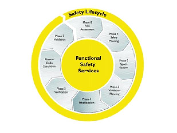
The reality is we must take some essential steps, in order to arrive at the correct safety solution and put it into action. That is where Phoenix Contact can help. Phoenix Contact defines functional safety as a safety life cycle. The safety life cycle shows eight phases dependent on whether safety-related software is used or not.
Here are a few examples of what these stages involve.
Phase 0 – Risk Assessment
A risk assessment is required to identify specific hazards that anyone coming into contact with the machine will be exposed to.
Typical examples are:
- Trapping
- Crushing
- Heat / Cold
- Electrical.
There are many types of risk assessment format available. You can download the HRN (Hazard Rating Number) example by clicking here.
Also, always refer to the latest Risk assessment standards, currently BS EN ISO 12100:2010. This offers loads of information around hazard identification and how to use this information.
Phase 1 – Safety Planning
Now you can use the risk assessment to decide how you will protect against the hazards identified. Many hazards can be eliminated at this stage and designed out. The mechanical design can have an even larger impact than fitting electrical safety measures to compensate later on.
This is where you need to decide on the Category B to 4 and Performance level (PL) ‘a’ to ‘e’. We should also refer to BS EN ISO 13849-1 for general principles of design during this part of the process.
*Remember: Category refers to architecture – Single/dual channel, for example.
Use our ‘Safety Application Guide’ for category definitions and more.
Performance level refers to the product capability. The typical lifetime of a mission or mission time is 20 years. This means all safety components used must last for this period, based on intended use. You will need the B10d / Mttfd figures from the component manufacturer to be able to confirm this.
Phase 2 – Specification
Using the intended machine design, you can now begin to decide on the hardware to best suit the requirements of your machine. For smaller machines, a single safety relay may do the job or, if you have a larger system, a configurable safety controller may be more suitable
Free software, such as SISTEMA, can be used to check the suitability of your chosen products; using the Phoenix Contact SISTEMA library, safety calculations are made even easier.
To download the library, click here. and then scroll down to ‘Software’ and click the box next to ‘Universal database VDMA66413’; now click the download button.
So that gives you an example of the first stages. Phoenix Contact can provide support throughout this whole process, as well as providing hardware solutions to fit your safety applications.
Want the latest machine building news straight to your inbox? Become a MachineBuilding member for free today >>


